Steering Gears
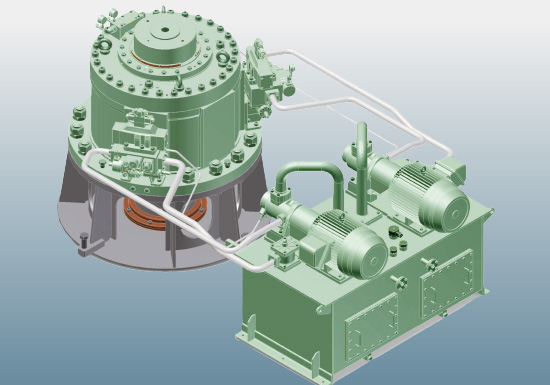
Foundation Integrated J-type Rotary Vane Steering Gears
History of Rotary Vane Steering Gears in our Company
Having obtained the grant of working license for the technology of Fish Tail Rudders and Vectwin Rudder Systems from Mr. Peter Bingham, England, in 1987, our Company first developed piston type steering gears of a large rudder angle on its own (Japanese patent) for coping with the said rudders, and promoted sales of the rudders and the steering gears in package, and further promoted technical development.
In the meanwhile, as a result of investigation on what a steering gear most adaptable is, to such a large rudder angle, the Company came to a conclusion that adoption of rotary vane steering gears is indispensable, and that it came to such judgment that the design of Frydenbo Company, Norway, is the highest for rotary vane steering gears. Thus our Company obtained the manufacturing and sales right in Japan for Frydenbo rotary vane steering gears in 1990. After that, however, the standard ranges and the license-granted ranges of the Frydenbo steering gears were considerably changed due to the change of the management of Frydenbo Company.
Hence our Company made propositions on solutions of the various problems to the new management of Frydenbo Company, in view that our Company was being responsible for supplying rotary vane steering gears to customers in Japan, and at the same time, promoted our Company’s own technical development by virtue of the subsidy from the Nippon Foundation on the basis of our Company’s actual results extending over many years. In the meanwhile, many Japanese patents have been applied and filed.
As a result, it has come to be possible for our Company to design and manufacture rotary vane steering gears.
Our Company puts it in practice to manufacture and sell rotary vane steering gears in Japan on the basis of the results of technical development as a steering gear most conformable to Fish Tail Rudders and Vectwin Rudder Systems.
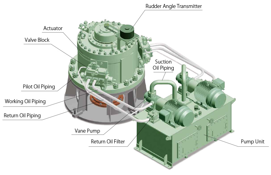
Special Features of Actuators
Stable operation is realized by adoption of a valve block system for a hydraulic system.
Higher reliability is secured by adoption of Thorflex seals of Thordon Bearings Inc.
- Torque characteristics are extremely rational.(Developing torque is not affected by rudder angles.)
- The most suitable construction for large rudder angles
- Extremely simple construction
- Rudder carrier function is incorporated in an actuator.
- Internal elements are only a rotor and seals.
- A control valve, an auto-lock valve, a flow control valve, a safety valve, etc. are accumulated in a valve block attached to each side of actuator.(Rationalization of a piping system, and adjustment and repair of valves become easy.)
- Hydraulic source for sealing, and its control device are provided outside an actuator.(Easy inspection and maintenance)
- V-type seals and a 2-stage sealing system are adopted for rotor gland seals. (Reliability is increased.)
- Thorflex seals of Thordon Bearings Inc. having plenty of actual results are adopted.
- Rational shape of seals and sealing system based on the actual results of many years are adopted.
- Such a sealing system that, in an emergency, even a bottom ring seal can be replaced on the sea is adopted, resulting in increase in reliability.
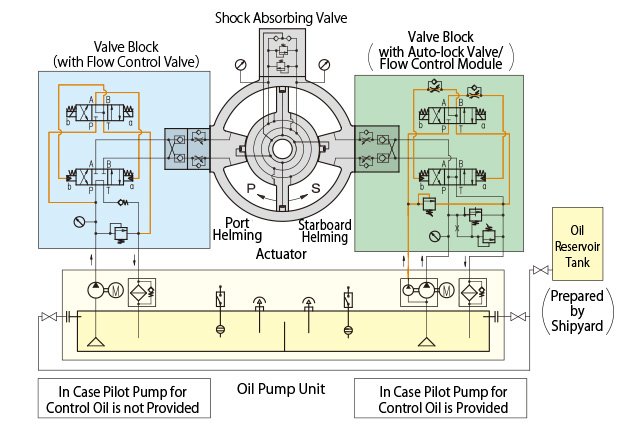
Special Features of Working Oil and Control Oil System
The system brings stable operation, energy-saving effect, and external cooling effect.
- Such a system is adopted that control oil system is provided independently of a working oil system.
- Energy-saving effect is created because working oil is not employed as control oil.
- By virtue of valve blocks directly attached to an actuator, rationalization of an external piping system is possible, and at the same time, cooling effect is obtained by circulation of working oil in external piping.
- A pressure valve as the source of sealing oil pressure is provided outside an actuator, and hence rationalization and increase in reliability of the system become possible.
- Bearing performance is improved because working oil is introduced into bearing rooms.
Special Features of Pump Unit
Vane-type pumps of high reliability are employed.
- Standard type vane pumps are adopted, which are optimum for an open circuit hydraulic system.
- Pumps are mounted on the tank top, this being possible from the characteristics of a vane type pump.
- A working oil pump and a control oil pump are independently provided respectively, and arranged in tandem.
- Easy inspection and repair because of simple constitution(This has been proved by plenty of the actual results.)
Realized Rationalization of Installing and Outfitting Work
Reduction of a working period and decrease in man-hours for installing and outfitting work are possible.
- Rationalization of installing and outfitting work is realized because an actuator itself holds function of rudder carrier, and that a steering gear integrates its foundation.
- Outfitting work is easy because it does not require skill-needing alignment work, and furthermore, boring work is not needed.
- Citing an instance of rationalization of installing and outfitting work in case of a 50,000 dwt bulk carrier:
- Reduction in man-hours: 100 man-hours
Reduction of working period: 1 week
Particulars of J-type Rotary Vane Steering Gears
It has been proved that rudder performance (ship’s maneuverability) is much improved by means of increasing a rudder angle to 2×45° or 2×70° from the conventional rudder angle of 2×35°. Rotary vane steering gears can easily cope with such a large rudder angle.
-
Remarks:
- Type J-2 holds 2 vanes, and Type J-3 holds 3 vanes.
- Design pressure depends on ranges of steering gears, but is about 8MPa.
- Safety valve setting pressure is 125% of design pressure.
| Type | Design TorquekN-m(t-m) | Max. Rudder Angle(deg.) |
Max. Rudder Stock Dia.(mm) |
Elect. Motor (1 motor normally used)Rating(kW×No.) |
External Dimension(mm) | Weight(kg) | Pump Unit Dimension(BredthxLengthxHeight) (mm) |
||
|---|---|---|---|---|---|---|---|---|---|
| Actuator Height(A) |
AcTuator Max. Breadth(B) |
Actuator | Pump Unit | ||||||
| JS-1 | 14.7(1.5) | 2×68 | 100 | 1.5×2 | 310 | 840 | 280 | 135 | 530×550×615 |
| J2-3D | 27.0(2.8) | 2×70 | 160 | 2.2×2 | 432 | 1,140 | 700 | 310 | 750×1,040×950 |
| J2-5D | 45.0(4.6) | 2×70 | 160 | 3.7×2 | 432 | 1,140 | 700 | 400 | 750×1,040×950 |
| J2-7.5D | 70.5(7.2) | 2×70 | 180 | 5.5×2 | 520 | 1,200 | 875 | 450 | 750×1,190×970 |
| J2-10D | 100.9(10.3) | 2×70 | 210 | 5.5×2 | 710 | 1,300 | 1,460 | 450 | 750×1,190×970 |
| J2-15D | 149.5(15.2) | 2×70 | 280 | 7.5×2 | 815 | 1,530 | 2,480 | 800 | 950×1,330×1,150 |
| J2-22D | 203.8(20.8) | 2×70 | 280 | 11×2 | 815 | 1,530 | 2,480 | 850 | 950×1,420×1,180 |
| J2-30D | 329(33.6) | 2×70 | 390 | 15×2 | 930 | 1,755 | 4,150 | 1,000 | 950×1,420×1,230 |
| J2-40D | 396(40.3) | 2×70 | 390 | 15×2 | 1,030 | 1,755 | 4,550 | 1,100 | 900×1,640×1,270 |
| J2-55D | 570(58.1) | 2×70 | 420 | 22×2 | 990 | 2,100 | 4,840 | 1,200 | 960×1,700×1,340 |
| J2-70D | 679(69.2) | 2×70 | 450 | 30×2 | 960 | 2,260 | 6,830 | 1,470 | 1,020×1,700×1,370 |
| J2-90D | 875(89.2) | 2×70 | 490 | 37×2 | 1,110 | 2,260 | 7,500 | 1,750 | 1,090×1,720×1,470 |
| J3-34D | 371(37.8) | 2×45 | 390 | 15×2 | 930 | 1,760 | 4,415 | 1,150 | 1,090×1,720×1,471 |
| J3-45D | 494(50.4) | 2×45 | 390 | 18.5×2 | 930 | 1,760 | 4,415 | 1,150 | 900×1,700×1,290 |
| J3-50D | 556(56.7) | 2×45 | 390 | 22×2 | 930 | 1,760 | 4,415 | 1,150 | 900×1,700×1,291 |
| J3-60D | 593(60.5) | 2×45 | 390 | 22×2 | 1,030 | 1,760 | 4,825 | 1,200 | 960×1,700×1,340 |
| J3-65D | 667(68.1) | 2×45 | 390 | 30×2 | 1,030 | 1,760 | 4,825 | 1,250 | 960×1,700×1,341 |
| J3-78D | 764(78.0) | 2×45 | 450 | 37×2 | 960 | 1,900 | 6,900 | 2,150 | 1,700×1,800×1,530 |
| J3-85D | 855(87.2) | 2×45 | 420 | 37×2 | 990 | 1,850 | 5,320 | 1,750 | 1,090×1,720×1,470 |
| J3-95D | 962(98.2) | 2×45 | 420 | 37×2 | 990 | 1,850 | 5,320 | 1,750 | 1,090×1,720×1,471 |
| J3-105D | 1,018(103.8) | 2×45 | 450 | 45×2 | 960 | 1,900 | 6,900 | 2,150 | 1,700×1,800×1,530 |
| J3-115D | 1,145(116.9) | 2×45 | 450 | 45×2 | 960 | 1,900 | 6,900 | 2,150 | 1,700×1,800×1,531 |
| J3-135D | 1,313(133.8) | 2×45 | 490 | 55×2 | 1,110 | 1,900 | 7,500 | 2,350 | 1,790×1,900×1,560 |
| J3-150D | 1,477(150.7) | 2×45 | 490 | 55×2 | 1,110 | 1,900 | 7,500 | 2,350 | 1,790×1,900×1,561 |
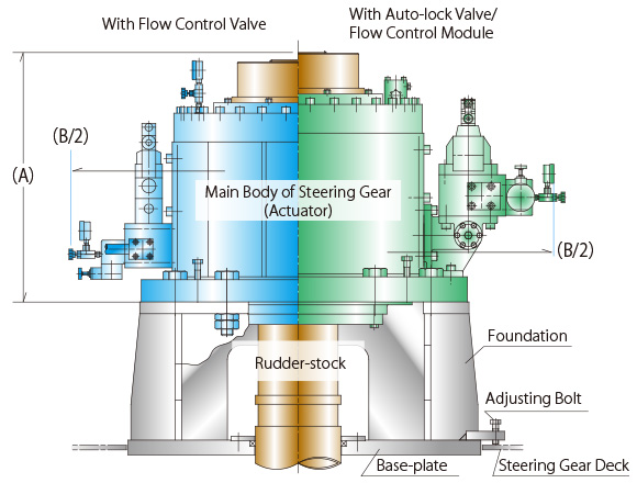
Installation
An installation hole is provided on the steering gear deck, and the base-plate of the steering gear foundation is inserted into the hole. After alignment and position adjustment, the base-plate is welded to the steering gear deck.
<Alternative Method>
Such a method is also possible that the base-plate is put on the steering gear deck, and position to be installed is determined by means of adjusting bolts provided on the base-plate.